Solar Power for Telecom Towers in Nigeria: PV Sizing, Battery Autonomy & 24/7 Site Reliability
Solar for Telecom Towers in Nigeria: PV & Battery Design
Learn how to design solar power for Nigerian telecom towers, estimate PV capacity and battery autonomy, integrate DC power systems, coordinate backup and monitor performance.
Solar Power for Telecom Towers in Nigeria: PV Sizing, Battery Autonomy & 24/7 Site Reliability
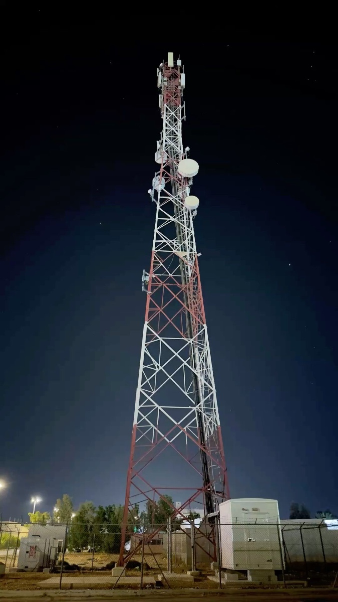
A mobile network tower cannot simply switch off when the sun sets. Radio equipment, transmission links, control systems and site auxiliaries need dependable power day and night. At many Nigerian sites, weak grid supply and diesel-generator dependence make that requirement expensive and operationally difficult.
A solar-hybrid power system can reduce generator runtime, but telecom sites need a different design approach from a typical home solar installation. The load is continuous, outages have service consequences, batteries must be monitored closely, and the power system often interfaces with an existing -48 V DC telecom bus and rectifier plant.
This guide explains how to assess a Nigerian telecom site, estimate its solar and storage needs, integrate solar with the existing DC power plant, retain dependable backup, and measure whether a retrofit is performing as expected.
Why telecom tower power is a live Nigerian engineering issue
Public community discussions add another perspective. A long-running Nairaland thread about telecom masts raised concerns about generator noise and fumes near homes, while another discussion asked about diesel consumption at telecom sites. These are qualitative community signals, not a measure of current search volume, but they show that tower energy is both an engineering and a local-operational issue.
The commercial opportunity is not to promise that solar eliminates every outage. It is to engineer a system around the actual site load, local solar resource, required autonomy, existing equipment and a realistic backup strategy.
Step 1: Audit the live site before selecting equipment
Do not size a telecom tower from a generic ‘standard site’ figure. Two sites with similar coverage can have different radio configurations, transmission equipment, cooling loads, grid availability and traffic profiles. Start with an energy audit of the actual site.
Record the DC load at the rectifier or power-system output over several representative days.
Separate the base telecom load from variable loads such as air conditioning, cabinet cooling, lighting and auxiliary equipment.
Record grid availability, generator run hours, fuel deliveries and any periods when equipment has been powered down to conserve energy.
Identify the existing rectifier plant, DC bus voltage, battery strings, controller and approved solar-input options.
Review the manufacturer’s operating limits, alarms, charging settings and warranty conditions.
Check the physical site for solar-array space, cable routes, drainage, access for maintenance and the environmental conditions around batteries and power electronics.
A logger or power-system telemetry can reveal the actual load curve. A short audit is better than guessing, although sites with seasonal cooling changes, new radio additions or unstable grid supply may need a longer observation period.
Step 2: Understand the telecom DC power architecture
Many telecom base stations use a nominal -48 V DC distribution system. Grid or generator AC is normally converted by a rectifier plant, and the DC bus supplies the radio and transmission equipment while charging the battery bank. The exact arrangement depends on the site and equipment manufacturer.
Solar can be added through a compatible DC-coupled solar controller or through an approved hybrid power system that coordinates PV, rectifiers, batteries and generator operation. The designer must confirm that the proposed equipment supports the site’s bus voltage, grounding arrangement, charging profile, current limits, monitoring protocol and protection scheme.
Do not connect a residential inverter or generic charge controller directly to a telecom DC bus simply because the nominal voltage appears compatible. Telecom power systems are engineered systems; compatibility and fault coordination must be verified with the equipment documentation and site owner.
Step 3: Calculate the site’s daily energy demand
For a continuous load, a useful first estimate is average power multiplied by 24 hours. For example, a measured average load of 2.5 kW consumes:
2.5 kW × 24 hours = 60 kWh per day
This is an illustrative calculation, not a claim about a particular Nigerian tower. The actual figure must come from the site audit. If cooling cycles, radio traffic, transmission equipment or future capacity additions change the load, the energy estimate should reflect those changes.
Keep average energy and peak power separate. Daily kWh helps determine how much energy PV must generate and how much storage is required. Peak kW and DC current help determine the ratings of converters, rectifiers, busbars, protective devices and other power equipment.
Step 4: Make a preliminary PV estimate using local assumptions
A first-pass PV estimate can be calculated from daily energy demand, the site’s effective peak-sun-hours assumption and an overall performance factor that accounts for system losses.
For the illustrative 60 kWh/day site, assume 5 effective peak-sun-hours and a 0.75 overall performance factor. The preliminary array estimate is:
60 ÷ (5 × 0.75) ≈ 16 kWp
This is a planning estimate only. Five peak-sun-hours is an assumption for this example, not a guaranteed Nigerian daily value. The final design should use location-specific monthly solar-yield data, shading assessment, array temperature effects, module layout, controller limits and expected battery-recharge needs.
A design that merely matches average daily consumption may not recover the battery quickly after a prolonged low-solar period. The designer should model typical and poorer production periods and decide how much generator support is needed to restore reserve.
Step 5: Size battery autonomy around the required service level
Battery autonomy is the time the battery can support the site load without adequate PV, grid or generator input. It should be chosen from the site’s required resilience, the reliability of other sources, the consequences of a site outage and the operator’s maintenance response time.
For an illustrative continuous load of 2.5 kW and a target of 12 hours of battery support, the energy delivered to the load is:
2.5 kW × 12 hours = 30 kWh
If the simplified design assumes 90% conversion efficiency and 80% usable battery energy, the nominal storage estimate is:
30 ÷ (0.90 × 0.80) ≈ 41.7 kWh
This is an illustrative energy calculation, not a battery-bank specification. The final design must account for the actual DC architecture, allowable depth of discharge, battery ageing, temperature, current limits, reserve margin, charging rate and the manufacturer’s recommendations. If the telecom equipment is supplied directly from a DC bus, the real conversion path may differ from the simplified example.
Autonomy should not be chosen in isolation. A battery sized for one night may be insufficient during consecutive low-solar days. In many sites, the best design is a coordinated system in which solar supplies the daytime load and recharges storage, the battery bridges gaps and covers the night, and a generator remains available for extended poor-production periods or equipment faults.
Step 6: Coordinate solar, rectifiers, batteries and generator control
A telecom hybrid controller should manage the available sources without violating equipment limits or allowing the DC bus to fall below the required operating range. The operating sequence must be defined and tested, not left to assumptions.
Solar should contribute energy when available while respecting the DC bus and battery charging limits.
The rectifier plant should supply the required load and charge batteries according to approved settings when grid or generator power is available.
Generator start and stop thresholds should preserve a reserve rather than waiting until the site is already close to failure.
Generator minimum run time, cooldown, failed-start alarms and restart logic should be configured according to the equipment and site operating plan.
The controller should prevent conflicting charging commands or unsafe interactions between sources.
The exact control sequence varies by manufacturer and topology. A retrofit should be reviewed with the site owner and the suppliers responsible for the existing rectifier, battery and generator controls.
Step 7: Monitor the system remotely and respond to alarms
A remote monitoring system is especially valuable when sites are geographically dispersed. It can help operators see whether the problem is low PV production, battery degradation, a failed rectifier, generator trouble, excessive auxiliary load or a communication issue.
Depending on the equipment, useful telemetry may include PV power and energy, DC bus voltage and current, battery state of charge, battery temperature, rectifier status, generator run hours, fuel level, cabinet temperature and door or system alarms. Interfaces may include SNMP, Modbus or a vendor-specific protocol.
Monitoring only creates value if somebody acts on the information. Define alarm thresholds, escalation routes, maintenance responsibility and response targets. A dashboard that records a low-battery alarm but does not trigger a response will not protect network availability.
Step 8: Engineer the site for heat, weather and maintainability
Telecom sites can operate in hot, dusty, humid or remote environments. Battery and power-electronics performance depends on the equipment’s specified temperature range and ventilation. Solar modules, mounting structures, enclosures and connectors must be selected for the actual site conditions.
The project plan should cover safe access, array cleaning, inspection of mounting hardware, battery-condition checks, controller firmware and configuration records, spare-parts availability and end-of-life battery handling. A system that is difficult to maintain may lose performance long before its expected design life.
Where equipment is installed outdoors, the designer should account for rainfall, drainage, wind loading, corrosion, dust ingress and physical access. Electrical safety, earthing, surge protection and inspection must follow applicable requirements and the equipment manufacturer’s instructions.
Illustrative engineering review: a rural telecom site in Kwara State
This is a hypothetical design scenario only. It is not a claim that Zookie Solar completed a telecom tower project.
Imagine a rural telecom site in Kwara State with an audited average DC load of 2.5 kW, intermittent grid supply and a generator that runs for long periods. The site owner wants to reduce fuel use without sacrificing network availability.
The audit confirms the existing -48 V DC plant, battery condition, generator controls, daily load profile and available array space. The preliminary energy calculation is 60 kWh/day. Using the illustrative solar assumptions above produces a first-pass PV estimate of 16 kWp, while a 12-hour battery-support target produces a simplified nominal storage estimate of about 41.7 kWh.
Those figures would then be tested against location-specific solar yield, the existing rectifier’s solar integration capability, battery discharge limits, recharge time, generator fuel records and the operator’s required reserve. The final design might change substantially after that review.
Before handover, the team would test source transitions, low-battery alarms, generator start and stop logic, remote telemetry, and recovery after a simulated grid interruption. Baseline fuel use and generator runtime would be recorded so that post-installation performance can be measured against the same operating conditions.
The objective is not a headline panel count. It is a measured reduction in generator runtime while maintaining the site’s required power quality and resilience.
How to assess savings without relying on sales promises
The business case should be built from the site’s records. Establish the baseline for diesel consumption, delivered fuel cost, generator maintenance, service visits and any grid energy charges. Then estimate the share of energy solar is expected to supply and the resulting change in generator runtime.
The investment appraisal should also include capital cost, battery replacement assumptions, equipment degradation, financing, monitoring, cleaning, spare parts and the cost of any remaining generator use. Payback varies with the actual load, solar resource, fuel logistics, battery design and site availability. Do not copy a percentage saving from another operator’s project and present it as a guaranteed result for your site.
Common mistakes in telecom solar retrofits
Sizing from a generic tower rating
Site configurations differ. Measure the actual DC load, cooling demand and energy use before selecting PV and storage.
Treating battery kWh as the only reliability measure
A battery must also deliver the required current, operate within its temperature and voltage limits, accept the charging rate and communicate correctly with the power system.
Assuming solar removes the need for a generator
Solar production changes with weather and seasons. A site with a strict availability target needs a documented plan for extended low-solar periods and equipment faults.
Ignoring added radio or cooling loads
New equipment can invalidate the original design. Record the baseline and require a power review before adding significant loads.
Installing monitoring without an operations process
Alarms need ownership, escalation and response. Otherwise, faults may remain undetected until the site loses service.
What to include in a telecom tower solar proposal
Measured site load profile and daily energy estimate.
Existing DC bus, rectifier, battery and generator architecture.
PV capacity, yield assumptions and monthly production estimate.
Battery capacity, autonomy assumptions, current limits and replacement plan.
Source-control sequence and generator operating logic.
Remote monitoring, alarm escalation and maintenance responsibilities.
Commissioning tests, baseline fuel records and post-installation performance reporting.
Clear exclusions, site-access requirements, safety documentation and warranty conditions.
For a portfolio of sites, the proposal should distinguish between site types rather than assume one configuration will fit every location. A repeatable design framework is useful, but each deployment still needs verification against its measured load and operating conditions.
Final takeaway
Solar-hybrid power for telecom towers is a specialised engineering application. It combines a continuous critical load, a DC power architecture, battery autonomy, solar-resource modelling, generator control and remote operations. The right system is sized from real site data and tested against the network operator’s service requirements.
For Nigerian tower owners, infrastructure companies and telecom contractors, a credible retrofit proposal should show how the design will reduce generator runtime, preserve DC power quality, manage low-solar periods and alert the operations team before a developing fault becomes a site outage.
Zookie Solar Ltd provides solar system design, equipment supply, installation and maintenance. If your organisation is evaluating solar for telecom or other critical remote infrastructure, share the site load profile, existing power architecture, generator records and required autonomy so the system can be assessed against actual operating conditions.
Built on Power. Driven by Excellence.
How to Match a Lithium Battery to a Solar Inverter in Nigeria: BMS, Voltage, CAN & RS485 Guide