Solar Cable Sizing in Nigeria: How to Choose the Right Cable, Voltage Drop & Protection for 2026 Installations
Introduction
A solar system can have excellent panels, a premium inverter and a high-quality lithium battery—and still perform badly if the wiring is poorly designed.
Cable selection is one of the less glamorous parts of a solar installation, but it affects safety, efficiency, charging performance, inverter reliability and the amount of energy that actually reaches the loads.
This matters in Nigeria because solar installations are increasingly moving beyond small backup systems into larger residential, commercial and industrial projects. Current Nigerian installation guidance and training materials continue to emphasise cable sizing, voltage-drop calculations, correct protection and professional commissioning. NEMSA also continues to enforce technical standards and inspect electrical and renewable-energy installations.
For a buyer, the practical question is not simply “What size cable do I need?” It is:
What cable size, insulation type, protection and installation method are appropriate for this exact current, voltage, distance and environment?
Why Cable Size Matters in a Solar System
A cable has to carry electrical current safely without excessive heating, while also keeping voltage drop within an acceptable range.
An undersized cable can cause:
• excessive voltage drop
• energy losses
• overheating
• nuisance inverter alarms or shutdowns
• slower or incomplete battery charging
• reduced inverter performance
• insulation deterioration
• connector and terminal heating
• increased fire risk
Nigerian electricity installation standards state that conductor size should be selected so its current-carrying capacity, after applicable installation factors, is not less than the maximum sustained current expected in the circuit. The same standards also require the cable voltage rating to be appropriate for the circuit and the insulation/protective covering to suit the installation environment.
In other words, “the cable fits the terminal” is not an engineering calculation.
The Four Things That Determine Solar Cable Size
1. Current
Higher current generally requires a larger conductor.
A basic relationship is:
**Current = Power ÷ Voltage**
For example, ignoring losses for a simple illustration:
5,000W ÷ 48V ≈ 104A.
Once inverter efficiency and operating conditions are considered, the actual battery-side current can be higher.
2. Cable length
The longer the cable run, the greater the resistance and potential voltage drop.
A cable that works perfectly for a short battery-to-inverter connection may be unsuitable for a much longer run.
3. Voltage
Higher system voltage allows the same power to be transmitted with lower current.
For example:
5,000W ÷ 48V ≈ 104A
while:
5,000W ÷ 24V ≈ 208A.
That is one reason higher-voltage architectures become attractive as system power increases.
4. Installation conditions
Cable selection also depends on temperature, whether cables are enclosed or in free air, grouping, exposure to sunlight, mechanical protection, moisture and other installation conditions.
The final cable size should therefore be selected from the applicable cable rating and voltage-drop calculations—not from a generic chart alone.
Which Solar Cables Are We Talking About?
A solar installation normally contains several different cable circuits, and they do not all need the same cable.
PV array cables
These connect the solar modules or strings to the combiner, isolator, MPPT or inverter.
They must be suitable for the DC voltage, current, outdoor exposure and temperature of the PV installation.
Battery-to-inverter cables
These can carry very high DC current, especially on 24V and 48V battery systems.
For a 5kW inverter operating from a 48V battery, the battery-side current can be around 100A or more depending on efficiency and operating conditions.
AC inverter output cables
These carry the inverter's AC output to the distribution board or designated loads.
The correct size depends on the inverter output current, phase arrangement, cable length, installation method and applicable protective-device requirements.
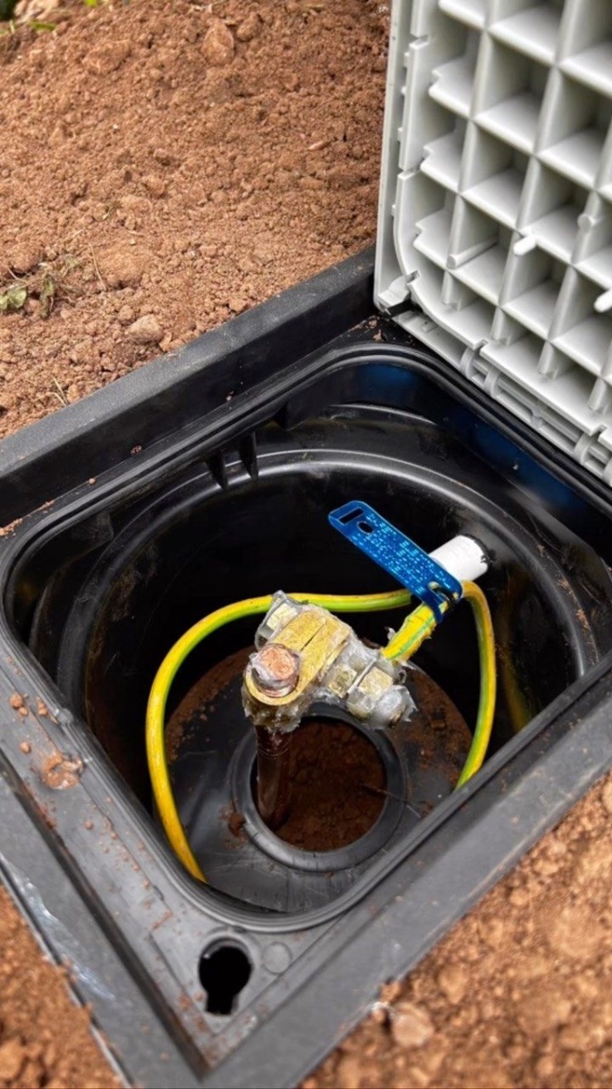
Earthing and bonding conductors
These are part of the safety system and should be selected according to the applicable electrical design and protection requirements.
One cable size cannot safely be used for every section simply because the system is called “5kVA solar.”
Illustrative Case Study: Why a 5kVA System Does Not Have One Universal Cable Size
This is an illustrative engineering case study, not a claim that Zookie Solar completed this project.
Imagine two customers who both purchase a 5kVA, 48V hybrid inverter.
Customer A places the battery 1.5 metres from the inverter.
Customer B puts the battery in a separate equipment room 8 metres away.
The inverter is the same. The battery voltage is the same. The rated power is the same.
But the cable design cannot automatically be identical.
Customer B has a substantially longer DC run, which increases resistance and voltage drop. The engineer may need a larger conductor to keep the voltage drop within the design limit.
This is why a quotation that says only “battery cable: 25mm²” without stating the cable length, current and design basis does not tell the full story.
How to Calculate Voltage Drop
For a simple two-conductor DC circuit, a commonly used approximation is:
**Voltage drop = 2 × L × I × ρ ÷ A**
Where:
• **L** = one-way cable length in metres
• **I** = current in amperes
• **ρ** = conductor resistivity
• **A** = conductor cross-sectional area in mm²
For copper at approximately 20°C, a commonly used resistivity value for basic calculations is about 0.0175 Ω·mm²/m. Actual cable resistance varies with conductor material, temperature and construction.
Illustrative calculation
Suppose:
• Current = 100A
• One-way length = 3m
• Copper cable = 35mm²
Then the approximate voltage drop is:
2 × 3 × 100 × 0.0175 ÷ 35
≈ 0.30V.
On a 48V system:
0.30 ÷ 48 × 100 ≈ 0.63%.
That is an illustrative calculation only. The final engineering selection must also check ampacity, temperature, installation method, protection and manufacturer requirements.
Why a 2-Metre Battery Run Is Not a Magic Rule
You may hear installers say that batteries should always be within 2 metres of the inverter.
Keeping a high-current battery connection short is generally sensible because it reduces voltage drop, cable cost and fault exposure.
But “2 metres” is not a universal substitute for calculation.
A 3-metre run with the correct conductor can be better engineered than a 1-metre run using an undersized cable.
Likewise, a longer run may be perfectly possible when the conductor is appropriately increased and the installation is properly protected.
The correct principle is:
Minimise unnecessary distance, then calculate the cable for the actual distance.
Battery Cable Sizing: The Part Buyers Should Take Seriously
Battery-to-inverter wiring deserves particular attention because low-voltage systems can carry very high current.
Consider an illustrative 10kW inverter on a 48V battery system.
Ignoring losses:
10,000W ÷ 48V ≈ 208A.
With inverter losses and operating conditions, the real DC input current can be higher.
At this current level, cable size, terminations, lugs, busbars, fuses and isolators become major engineering components.
This is why a large inverter should not be connected to a battery with ordinary household wiring simply because the insulation looks thick enough.
PV Cable Sizing Is Different From Battery Cable Sizing
A common mistake is to assume that because a battery cable needs 50mm², the solar-panel cable should also be 50mm².
That does not follow.
PV strings often operate at substantially higher voltage and lower current than the battery side.
For example, a hypothetical PV string may operate around 500V with a current of 13A, while a 48V battery may supply more than 100A to a high-power inverter.
The two circuits therefore have completely different electrical characteristics.
PV cable selection must consider:
• maximum PV current
• string configuration
• open-circuit voltage
• cable length
• ambient temperature
• installation method
• UV exposure
• connector compatibility
• voltage drop
• protection requirements
Why Cheap or “Half-Cut” Cable Can Be Dangerous
Cable size is about the actual conductor, not just the number printed on the insulation.
In the Nigerian market, installers and suppliers warn about poor-quality conductors that may contain less copper than their labelled cross-sectional area suggests.
A cheaper cable can therefore create a false economy.
Two cables may both be marked “35mm²,” yet their construction, conductor material, flexibility, insulation, temperature rating and actual electrical performance can differ.
For an expensive solar system, cable should be purchased from a reputable source and specified by an identifiable standard, construction and cross-sectional area—not simply by price per metre.
Cable Length Can Change the Cost of a Solar Installation
Long cable runs affect more than performance.
They can increase:
• conductor cost
• voltage-drop losses
• conduit or trunking requirements
• installation labour
• protection requirements
• termination points
• fault exposure
This is one reason good solar design considers equipment placement before installation begins.
For example, placing the battery and inverter close together may reduce the amount of expensive high-current DC cable required, while the solar array may be positioned farther away because the PV side can operate at a higher voltage.
The layout should be optimised electrically, not just aesthetically.
What About AC Cable Size From the Inverter to the Distribution Board?
The AC side needs its own calculation.
For a single-phase 5kW inverter at approximately 230V:
5,000W ÷ 230V ≈ 21.7A.
But that number alone does not determine the cable size.
The engineer must also consider:
• inverter maximum AC output
• continuous loading
• cable length
• voltage drop
• installation method
• ambient temperature
• grouping
• breaker rating
• phase configuration
• applicable standards
A three-phase commercial inverter has a different current calculation again.
Never choose the AC cable solely because another installer used the same size on a different project.
Protection Must Match the Cable
A properly sized cable can still be unsafe if the protective device is wrong.
The protection system should be coordinated so that a fault can be interrupted before the cable is damaged, while avoiding nuisance operation during normal conditions.
Depending on the system, protection may include:
• battery fuse or DC breaker
• PV string or array protection
• DC isolator
• AC breaker
• surge protection
• appropriate earthing and bonding
• equipment-specific protection
NEMSA's role includes enforcing technical standards and inspecting electrical installations, while current Nigerian safety efforts continue to emphasise competent professionals and the elimination of substandard installations.
The cable, fuse/breaker and installation method should therefore be treated as one engineering system.
Illustrative Failure Scenario: The Inverter Works—Until the Load Gets High
This is an illustrative scenario, not a completed Zookie Solar project.
A business installs a 5kVA hybrid inverter. At light loads, everything appears normal.
When the load rises toward 4–5kW, the inverter begins showing low-voltage warnings and eventually shuts down.
The owner assumes the battery is faulty.
During investigation, the battery voltage at the terminals is healthy, but the voltage measured at the inverter is significantly lower under load.
The engineer identifies excessive resistance in the DC connection caused by an unsuitable cable/run combination and/or poor termination.
The lesson is important:
A system can have a healthy battery and a good inverter but still suffer from a bad DC connection.
Voltage should be checked under meaningful load, not only when the system is sitting idle.
Why Cable Terminations Matter as Much as Cable Size
A correctly sized cable with a poor termination can still become a hot spot.
Common installation problems include:
• loose terminal screws
• incorrectly crimped lugs
• incompatible terminals
• exposed strands
• wrong lug size
• excessive bending at terminals
• poor connector engagement
• corrosion
• repeated thermal cycling
At high current, even a relatively small contact resistance can produce substantial heat.
For example, power lost at a connection follows:
**P = I²R**
At 100A, a connection resistance of only 0.001Ω produces:
100² × 0.001 = 10W.
That is 10W concentrated at one small connection point.
Professional crimping, correct torque and appropriate termination hardware therefore matter enormously.
How Nigerian Heat Affects Cable Selection
Nigeria's ambient temperatures can be high, especially in rooftop installations and enclosed equipment areas.
As conductor temperature rises, electrical resistance also increases.
That means a cable calculation based only on laboratory conditions may not tell the whole story.
Installers should account for the actual installation environment, including:
• rooftop temperature
• direct sunlight
• enclosed conduits
• cable grouping
• ventilation
• proximity to hot equipment
A cable route that is acceptable in a cool, open environment may require derating or a different conductor arrangement in a hot, crowded installation.
What Should Be Written in Your Solar Quotation?
A professional quotation should make the important wiring assumptions visible.
For a meaningful installation proposal, ask for:
• PV cable size and type
• battery cable size and type
• AC output cable size
• approximate cable lengths
• protective-device ratings
• isolator details
• cable termination method
• mounting/cable-management method
• earthing/bonding arrangement
• installation and commissioning scope
A quotation that simply says “complete cabling” makes it difficult to compare one installer with another.
The cheaper quote may simply contain smaller conductors or less protection.
Five Questions to Ask Your Solar Installer About Cabling
1. What is the maximum current on each cable run?
Ask them to show the calculation.
2. What is the one-way cable distance?
Cable length affects voltage drop and cost.
3. What voltage drop are you designing for?
Do not accept “the cable is thick enough” as the calculation.
4. What protective device protects this cable?
The breaker or fuse must be coordinated with the cable and equipment.
5. How will the cable terminations be made and tested?
Correct lugs, connectors, crimping and torque are part of a professional installation.
Illustrative 5kVA Installation: What an Engineer Should Calculate
This is an illustrative design example, not a Zookie Solar project.
Imagine a 5kVA, 48V hybrid system with:
• maximum inverter output: 5,000W
• battery voltage: approximately 48V
• battery-to-inverter distance: 3m one way
• PV array: several hundred volts DC at string level
• AC output: approximately 230V single phase
A professional design would calculate separately:
Battery side: expected maximum DC current, cable ampacity, voltage drop, fuse/breaker rating, termination method and battery manufacturer's requirements.
PV side: string voltage, current, maximum open-circuit voltage, cable ampacity, voltage drop, environmental rating, connectors and DC protection.
AC side: maximum output current, cable ampacity, voltage drop, breaker rating, isolation and distribution-board connection.
The final bill of materials should then follow those calculations—not the other way around.
When Should a Cable Be Upsized?
Upsizing may be appropriate when:
• the run is long
• current is high
• ambient temperature is high
• cables are grouped
• voltage drop is approaching the design limit
• future loading is expected
• the installation method reduces allowable ampacity
• the manufacturer's requirements call for a larger conductor
But bigger is not automatically better in every respect.
A very large conductor can increase cost, installation difficulty and termination requirements.
The correct objective is an appropriately sized cable that satisfies current-carrying capacity, voltage drop, environmental and protection requirements.
What a Proper Solar Cable Installation Should Look Like
A professional installation should be:
Correctly sized — based on current, distance, voltage drop and installation conditions.
Properly protected — with appropriate overcurrent protection, isolation and surge protection where required.
Well terminated — using suitable lugs/connectors, correct crimping and secure connections.
Mechanically protected — routed so that cables are not unnecessarily exposed to abrasion, sharp edges, water or physical damage.
Clearly identified — so future technicians can understand the system.
Documented — with cable sizes, protection ratings and relevant commissioning information.
NEMSA's current public guidance and services emphasise technical standards, inspection, testing and certification of electrical and renewable-energy installations. A quality solar project should be designed with that level of professionalism in mind.
Final Takeaway
The cable is not the part of a solar system to save money by guessing.
A solar installation is an electrical system, and every cable has a job: carry a defined current, over a defined distance, under defined environmental conditions, with acceptable voltage drop and appropriate protection.
For Nigerian homes and businesses, the most important lesson is simple:
Do not ask only, “What cable size do you normally use?” Ask, “What calculation supports this cable size for my installation?”
At Zookie Solar, we design the complete electrical path—from PV array and battery through inverter, protection and distribution—rather than treating cabling as an afterthought.
Planning a new solar installation or reviewing a quotation you already received? Contact Zookie Solar for a professional site assessment, engineering design and installation quotation.
Built on Power. Driven by Excellence.